SCME Development Plan
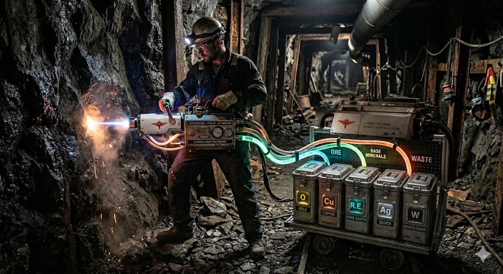
PoC v1 · planning SCME — Selective Mineral Extraction Point, extract, sort: the end-state is a laser/plasma head that ablates rock and routes the recovered material, element-by-element, into labeled collection bins.
This page is honest about the gap between that vision and what is buildable today. It pairs the concept render with a grounded, six-iteration surrogate-bench proof of concept that de-risks the core sorting physics before any plasma-phase hardware is attempted.
Vision / concept render — target hardware, not an existing build. From vision to bench Separation science routinely starts with safe liquid analogues. PoC v1 proves the controllable sort step with inert surrogates and current-limited electrical stages — the handheld laser-plasma head, dry-rock ablation, and in-line element ID are deliberately out of scope until the sorting core is repeatable.
Element targets
Au GoldCu CopperR.E. Rare EarthAg SilverW Waste / DarkSafety baseline: use non-hazardous surrogate media and enclosed, current-limited electrical stages for all early bench work. The HV / corona / ionizer stages (P2–P3) stay shielded and interlocked.
P1 Surrogate Baseline Bench · plannedP2 Charging Stage Integration · plannedP3 Field-Deflection Splitter · plannedP4 Sensing and Closed-Loop Control · plannedP5 Reliability and Serviceability Pass · plannedP6 PoC v1 Demonstration Build · plannedSurrogate Baseline Bench Build a safe, non-plasma baseline that proves extraction and two-way sorting with visible surrogate material.
Validates that a feed can be split into repeatable fractions at all — the core sort step behind the vision’s element bins.
Schematic [Feed Tank] -> [Peristaltic Pump] -> [Inline Mesh Filter]
-> [Transparent Test Cell] -> [Y-Manifold]
-> [Collection A] + [Collection B] Design Focus Use dyed water + mixed particle surrogates (fine glitter, larger polymer beads). Keep all tubing transparent for visual debugging and clog detection. Make manifold outlet lengths equal to remove geometry bias. BoM (Core) 1x 12V peristaltic pump (low-flow, chemically compatible tubing) 1x inline stainless mesh cartridge set (100-500 µm) 1x acrylic/polycarbonate test cell with threaded ports 1x Y-manifold, 2x collection bottles, silicone tubing set 1x DC power supply, clamps, spill tray, PPE (gloves/goggles) Test Setup Run fixed 2-minute cycles at 3 flow settings (low/med/high). Measure extraction ratio: solids captured in filter vs total input solids. Measure split ratio consistency: output mass/volume in A vs B across 5 runs. Acceptance Criteria (target) Split-ratio consistency within ±10% (mass/volume A vs B) across 5 consecutive runs. Extraction ratio (filter-captured solids / input solids) ≥ 80% at the chosen flow setting. No clogs or leaks across a full 2-minute cycle. Open Questions / Risks Do inert surrogate particles behave like real comminuted ore fractions? Does a liquid carrier transfer to a dry/plasma regime at all, or only validate the control logic? Charging Stage Integration Add a controlled charging/conditioning section before splitting to create measurable response contrast.
Validates that conditioning material gives the splitter a handle to act on — the surrogate stand-in for plasma ablation/ionization.
Schematic [Feed] -> [Pump] -> [Filter] -> [Conditioning Chamber]
-> [Grounded Drift Tube] -> [Y-Manifold] -> [A/B] Design Focus Add low-power corona ionizer module in a shielded enclosure. Use a grounded metal drift tube immediately after conditioning. Add removable module mounts so P1 baseline can be restored quickly. BoM (Core) 1x low-power ionizer/corona module with isolated PSU 1x grounded drift tube section (stainless/aluminum) 1x shielded enclosure + interlock switch for conditioning stage 1x inline current/voltage monitor for the conditioning module Test Setup A/B comparison: conditioning OFF vs ON with identical feed recipe. Record outlet turbidity/color difference between branch A and B. Log module current draw and thermal rise over 10-minute runs. Acceptance Criteria (target) Measurable, repeatable A/B contrast (turbidity/color) between conditioning OFF and ON. Conditioning module current draw and thermal rise stay within rated limits over 10-minute runs. Open Questions / Risks Is corona/ionizer conditioning a faithful stand-in for plasma ablation, or a different physics entirely? How sensitive is the A/B contrast to feed-recipe variation? Field-Deflection Splitter Replace passive Y split with an active deflection section that nudges conditioned flow toward selected outlets.
Validates active, controllable sorting into element-proxy fractions (light/mid/heavy) — the bench analogue of the Au/Cu/R.E./Ag/W bins.
Schematic [Conditioned Flow] -> [Deflection Cell: Plate + / Plate - ]
-> [Tri-Outlet Manifold: Light / Mid / Heavy element-proxy] Design Focus Use a narrow deflection cell with adjustable plate spacing. Move from 2-way to 3-way manifold for richer fraction output. Add manual knobs for plate voltage and flow rate as core controls. BoM (Core) 2x stainless deflection plates with insulated mounts 1x controllable HV DC module (current-limited) 1x tri-outlet manifold + three labeled collection vessels 1x compact enclosure fan and thermal sensor Test Setup Run a 3x3 matrix: three flow rates x three field strengths. For each run, measure collected volume and visible particle loading per outlet. Select control window that maximizes spread between light/mid/heavy outlets. Acceptance Criteria (target) Clear, monotonic separation between light/mid/heavy outlets across the 3×3 flow×field matrix. A control window exists where outlet loadings differ measurably by mass and by eye. Open Questions / Risks Does field deflection map onto element-wise sorting, or only onto size/density proxies? What plate field strengths stay safe at the target flow rates? Sensing and Closed-Loop Control Instrument the machine and automate setpoint tuning for stable fraction quality over time.
Validates real-time fraction sensing + feedback — the precursor to in-line spectroscopic (LIBS/XRF) element identification at the rock face.
Schematic [Inlet Sensor] -> [Controller] -> [Pump + Field Supply]
[Outlet A/B/C Sensors] -> [Controller Logging] Design Focus Use low-cost turbidity or optical density sensors on each outlet. Control pump PWM and field setpoint from a microcontroller. Implement simple feedback rule: keep target outlet turbidity within band. BoM (Core) 1x ESP32 or similar microcontroller board 4x turbidity/optical sensors (1 inlet + 3 outlets) 1x MOSFET pump driver board + isolated signal wiring 1x SD card module or USB serial logger Test Setup Execute 30-minute drift tests with deliberate feed concentration swings. Compare manual control vs closed-loop control on fraction stability. Track settling time after feed disturbance and overshoot percentage. Acceptance Criteria (target) Closed-loop control holds target outlet turbidity within band under deliberate feed swings. Settling time after a feed disturbance stays under target with bounded overshoot. Open Questions / Risks Do turbidity/optical proxies generalize to in-line spectroscopic (LIBS/XRF) element ID? Is the control loop stable across the full P3 operating window? Reliability and Serviceability Pass Prepare the assembly for repeatable daily operation with quick cleaning and reduced fouling.
Validates field-serviceability — the bench discipline a handheld/rig-mounted mining tool would need to survive real duty cycles.
Schematic [Feed] -> [Quick-Release Filter] -> [Condition + Deflect Core]
-> [Outlets] + [Bypass/Flush Loop] + [Drain] Design Focus Add bypass/flush loop for rapid decontamination between recipes. Switch to quick-release unions on all frequently serviced sections. Create a fixed wiring harness and labeled tubing map to cut setup errors. BoM (Core) Quick-connect unions, extra gaskets, check valves, drain valve Secondary rinse reservoir + flush pump path Spare filter cartridges and pre-cut tubing replacement kit Printed label set for electrical and fluid lines Test Setup Run 10 consecutive cycles with cleaning between each cycle. Measure turnaround time and carryover contamination after cleaning. Log leak events, clogs, and component swaps required per day. Acceptance Criteria (target) 10 consecutive cycles complete with cleaning between each and no unplanned component swaps. Carryover contamination after cleaning stays below a defined threshold. Open Questions / Risks Which components foul fastest, and do they have field-replaceable equivalents? Does daily-operation wear change separation performance over time? PoC v1 Demonstration Build Freeze a reproducible PoC v1 configuration and demonstrate extraction + sorting performance against defined acceptance criteria.
Validates the full extract → condition → sort → verify loop end-to-end — the minimum credible proof before any plasma-phase work begins.
Schematic [Recipe Prep] -> [SCME PoC v1 Core] -> [Fraction A/B/C]
-> [Offline Verification: mass, turbidity, image capture] Design Focus Freeze mechanical layout, wiring map, and control presets as v1. Produce one-page operator SOP: startup, run, shutdown, clean. Define pass/fail gate for repeatability and separation effectiveness. BoM (Core) Final integrated frame/enclosure with documented part numbers Calibrated sensors and verified power modules from prior phases Operator kit: PPE, cleaning consumables, spare critical parts Run log sheets/templates for reproducibility package Test Setup Perform three full demonstration days, each with at least five runs. Acceptance targets: stable outlet signatures, no unsafe trips, repeatable split profile. Publish v1 report: configuration, results, failure modes, next upgrade list. Acceptance Criteria (target) Three demonstration days, ≥5 runs each, with stable outlet signatures and no unsafe trips. Repeatable split profile across all demonstration runs. Published v1 report covering configuration, results, and failure modes. Open Questions / Risks What is the minimum credible evidence to justify any plasma-phase work? Which failure modes would block scale-up beyond the bench? ← Back to Hardware projects